

Check whether the local and remote interfaces use optical modules of different types from different vendors.SM and MM indicate single-mode and multimode, respectively. You can also view the label attached to an optical module to check whether it is a single-mode or multimode optical module. Generally, the handle of a multimode optical module is black and that of a single-mode optical module is blue. Generally, a single-mode optical fiber is yellow, and a multimode optical fiber is orange. Check whether the optical modules of the local and remote interfaces match the optical fibers connected to them.If the actual transmission distance exceeds 30 m, use an optical fiber with a longer transmission distance. For example, in the preceding command output, the transmission distance supported by the OM1 optical fiber is 30 m. View this field to determine whether the optical fiber length is within the allowed transmission distance range of the optical module. In the command output in step 2, the Transfer Distance field indicates the transmission distance supported the optical module. If the transmission distance between two optical modules exceeds the maximum distance they support, alarms on low optical power will be generated even if the optical modules have the same wavelength. Check whether the optical fiber length is within the allowed transmission distance range of the optical module.An unclean fiber connector may degrade the quality of optical signals or even cause link failures or error codes on the link. It is recommended that idle fiber connectors be covered with dust-proof caps to keep the fiber connectors clean. Remove and reinstall the optical fibers and optical modules and check whether the fiber connectors are damaged or contaminated, to determine whether the CRC error packets are caused by poor contact.Run the display interface transceiver verbose command to check whether the wavelengths of the optical modules at both ends are the same and whether the optical module information, such as the power, is normal.If they work in non-auto-negotiation mode, ensure that the interfaces work at the same rate and in the same duplex mode.

In this case, remove and reinstall the cables.Įnsure that optical interfaces at both ends of a link work in the same auto-negotiation mode. This is often caused by poor contact of network cables. It is normal if a few CRC error packets are received. If the error packet count keeps increasing, check the cable quality first. The CRC error packets are usually caused by interference of network cables. Run the display this interface command multiple times in the interface view to check the interface status, and check whether the discarded packet count and CRC error packet count at the physical layer keep increasing stably.

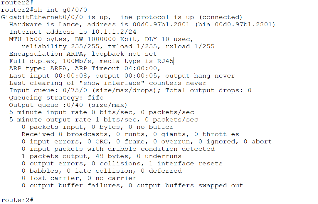
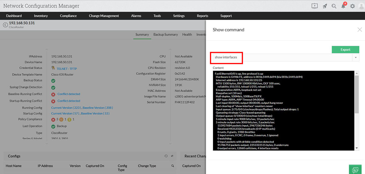
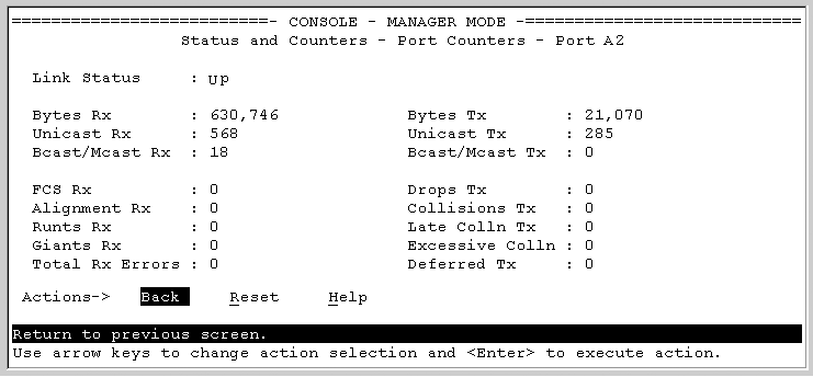
Input Flow-control: DISABLE, Output Flow-control: DISABLE IP Sending Frames' Format is PKTFMT_ETHNT_2, Hardware address is 00a0-c945-6101 Switch Port, PVID : 1, TPID : 8100(Hex), The Maximum Frame Length is 9216 dispaly interface 10ge 1/0/1ġ0GE1/0/1 current state : DOWN (ifindex: 36) Generally, CRC error packets indicate that service packets are lost on the link. You can view the CRC error packet statistics in the output of the display interface command.


 0 kommentar(er)
